
A structural frame analysis was carried out on a proposed boat cradle to assess its strength and stiffness under the specified operating and loading conditions. The assessment was performed using Autodesk Inventor Frame Analysis, with the structural model developed from fabrication drawings and a client-supplied STEP model.
The cradle was designed for a Safe Working Load (SWL) of 13.5 tonnes. In addition to assessing the design requirement, a conservative loading condition was investigated to provide further confidence in the structural performance of the cradle.
The analysis assessed stress and displacement throughout the frame, including the transverse boat-support beams and towing structure.
Structure Description
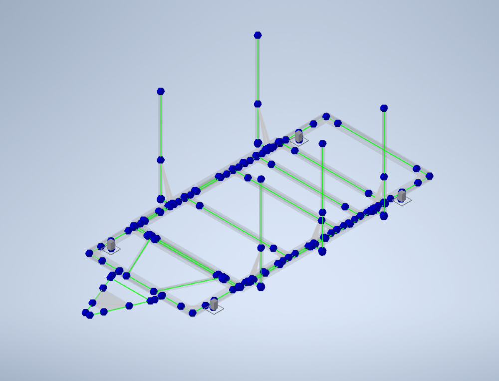
The boat cradle consisted of a fabricated structural steel frame designed to support and transport the vessel.
The primary structural components included:
- Longitudinal main frame members
- Eight transverse load-bearing beams
- Additional longitudinal strengthening members
- Vertical support posts
- Front towing frame
- Four castor support locations
The structural members were modelled using S355 structural steel, with a yield strength of 355 MPa.
Analysis Assumptions
The assessment focused on the global structural behaviour of the boat cradle.
Key assumptions included:
- Structural geometry was based on the fabrication drawing and STEP model supplied by the client.
- Primary structural members were represented using beam elements.
- S355 structural steel was assumed to behave as a homogeneous, isotropic and linear-elastic material.
- A conservative worst-case loading condition was adopted for the structural assessment.
- The boat load was assumed to be distributed equally across the eight transverse support beams and represented by equal downward point loads applied at the centre of each beam.
- Self-weight is included automatically through the assigned material properties and gravitational loading.
- The horizontal towing force is applied through the tow frame to represent the maximum operational winch loading. Dynamic effects associated with towing, acceleration, braking or impact loading are not considered unless otherwise stated.
- The four castor locations were treated as structural supports on a rigid, level surface.
- The assessment was performed as a linear static analysis. Dynamic, fatigue, impact and nonlinear effects were outside the scope of the assessment.
- Detailed verification of bolts, welds and secondary connection components was outside the scope of the global frame analysis.
- All welded or bolted connections provide sufficient strength for each junction.
Model Simplification
To provide an efficient assessment of the overall structural behaviour, the cradle was represented using a beam-element model generated in Autodesk Inventor Frame Analysis. Secondary details such as connection plates, gusset plates, bolts, welds, castor assemblies and small fabrication features were not explicitly modelled. Where required, custom nodes and rigid links were used to represent load transfer through gusset and bolted connection locations.
Loading Conditions
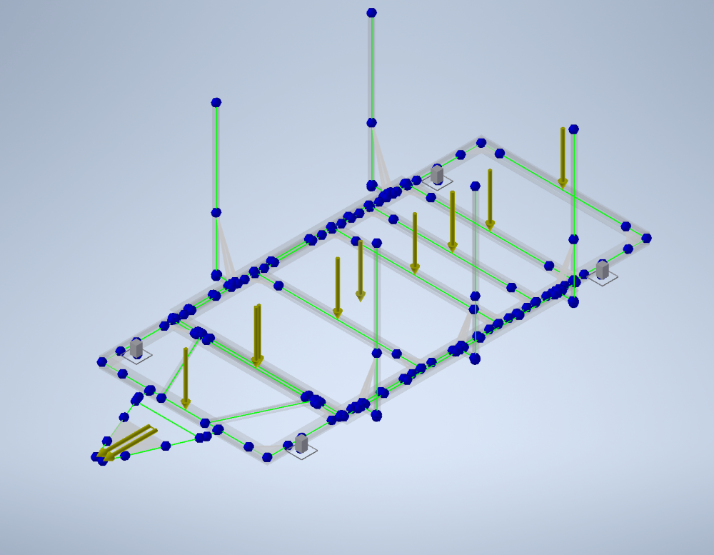
Fixed constraints were applied at the four castor mounting locations to represent the cradle supported on a rigid surface with the wheels fully prevented from moving during loading. Adopting a conservative worst-case loading condition, the analysis was carried out by applying:
- Concentrated vertical point loads at the centre of each of the eight transverse support beams
- Self-weight of the complete structural frame
- A 29.44 kN horizontal towing load as a uniformly distributed load along the top horizontal towing member
To evaluate the structural capacity beyond the design load, the applied point loads were progressively increased while monitoring the response of the governing transverse support beam. The loading was increased until the beam approached the adopted serviceability limit of L/300 while ensuring that the maximum stress remained below the 355 MPa yield strength of S355 structural steel. This occurred when the applied load on the governing transverse support beam reached 39.8 kN.
Frame Analysis
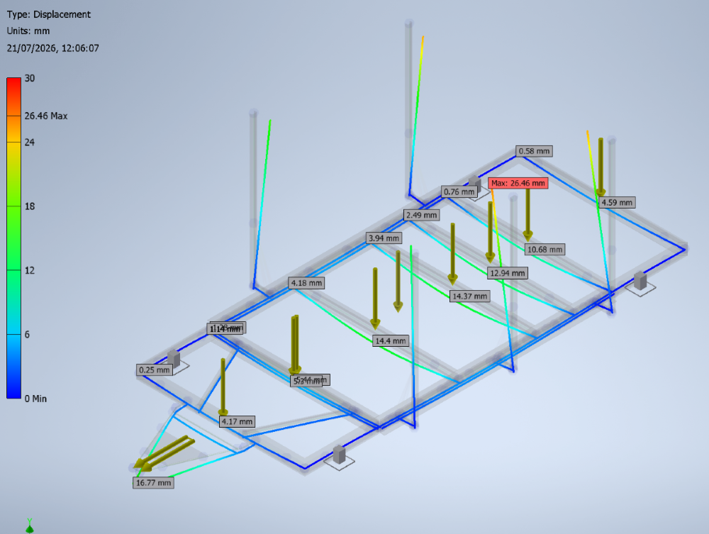
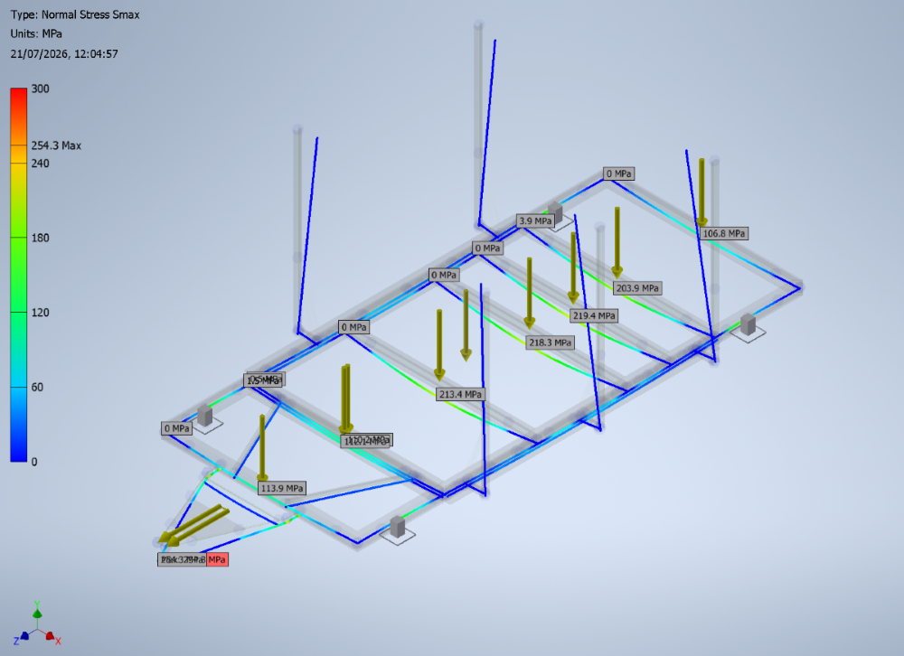
The assessment considered both the displacement and stress distribution within the frame to verify compliance with the adopted serviceability and strength criteria.
Larger displacements and maximum stress occurred at the vertical guide posts and towing assembly.
As the vertical guide posts members are intended only to provide lateral guidance and are not designed to carry the vertical boat load, their displacement and stress have a negligible effect on the structural performance of the cradle.
The localised displacement at the front towing assembly is expected as the towing member behaves as a cantilever and is subjected to the applied towing load. As this component is not part of the primary boat-supporting structure, the displacement does not significantly affect the load-carrying performance of the cradle.
The maximum relative deflection reported for the transverse support beams was 10.45 mm, remaining below the adopted serviceability limit of 10.46 mm (L/300).
The analysis identified a maximum stress of approximately 254.3 MPa around the front towing assembly, where the towing load is transferred into the main frame. The maximum stress within the transverse support beams was approximately 219.4 MPa.
Both values remained below the 355 MPa yield strength of S355 structural steel, indicating that the modelled primary structure remained within the elastic range under the adopted loading condition.
Results & Findings
The frame analysis indicated that:
- The boat cradle provided adequate strength and stiffness for its specified 13.5-tonne SWL
- Maximum stress remained below the 355 MPa yield strength of S355 structural steel
- The transverse support beams remained within the adopted L/300 deflection limit
- The analysis demonstrated an equivalent overall SWL of approximately 21.3 tonnes, after applying a 1.5 live-load factor
- Individual transverse beams were assessed with an SWL of approximately 2.7 tonnes per beam
- Larger local displacements occurred at the towing member and vertical guide posts; however, these did not govern the performance of the primary boat-supporting structure
Outcome & Value
The structural frame analysis provided:
- Verification of the cradle's global structural performance
- Assessment of stress and displacement under conservative loading conditions
- Evaluation of the primary transverse boat-support beams
- Assessment of the structural response to the towing load
- Identification of the governing structural areas
- Engineering evidence to support the proposed 13.5-tonne SWL
This case study demonstrates how Autodesk Inventor Frame Analysis can be used to assess fabricated steel structures efficiently, providing clear engineering evidence to support design decisions and confirm structural performance.